
Calibrating Directional Operating Boundaries Under Asymmetric Disturbance Regimes
Directional operating boundaries calibrate safe envelopes by contracting margins along vectors where disturbance amplitude outpaces recovery velocity.
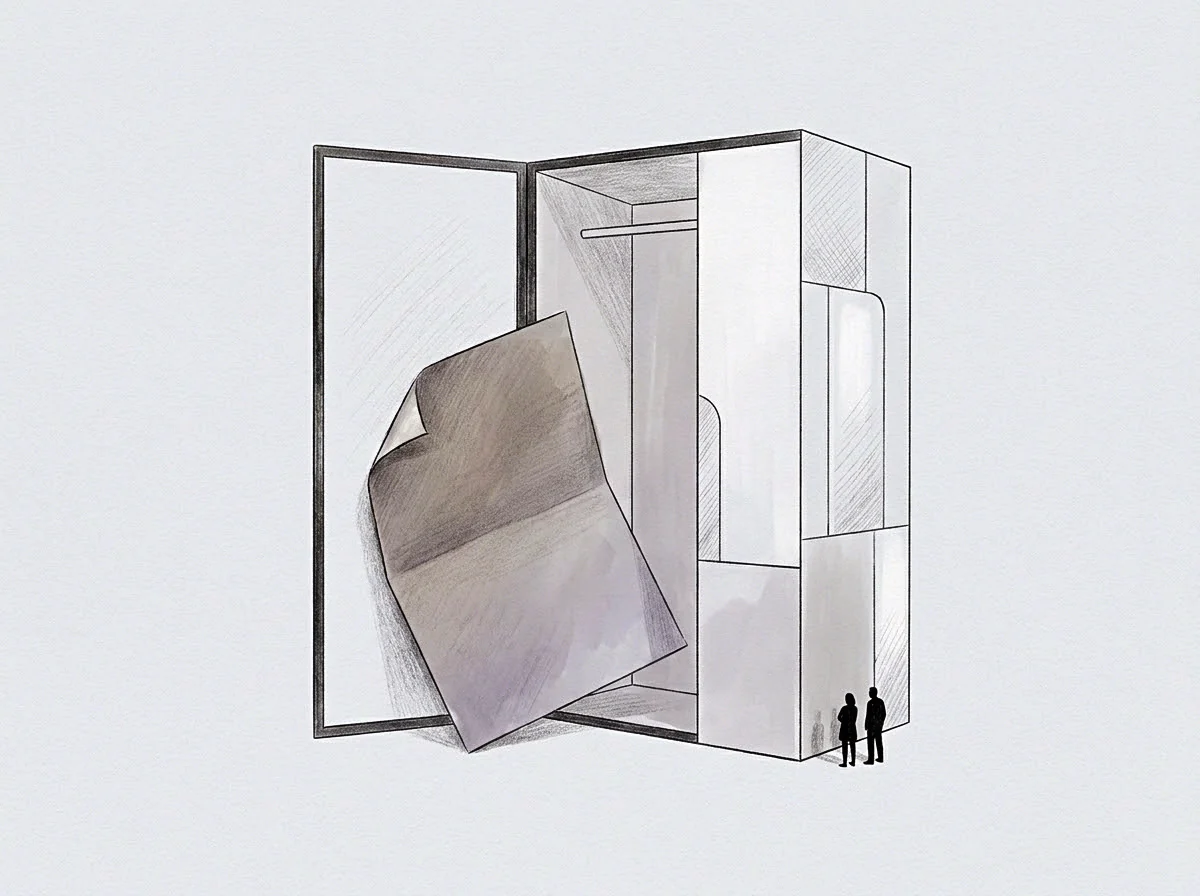
Hull
Asymmetric shocks deform operational capacity unevenly along directional axes. When an organisation encounters disturbances whose frequency and amplitude concentrate along a single vector, treating safety margins as uniform envelopes invites structural failure. Traditional reserve allocations assume isotropic risk distributions.
Real operating environments present directional shears where downside amplitude exceeds recovery velocity by an order of magnitude. A system subjected to persistent unidirectional load experiences non-linear stress accumulation along its exposed faces while maintaining idle capacity on its shielded flanks.
Calculating directional thresholds demands explicit modeling of recovery hysteresis. Exposure to a downside disturbance burns through liquid capital, operational attention, and systemic slack faster than replenishment schedules can replace them. A ten percent adverse displacement along a vulnerable axis can trigger cascading delays that take quarters to reverse.
Stabilisation requires pulling outer boundaries closer to the nominal setpoint on high-disturbance vectors, while permitting wider excursions on vectors that correct themselves quickly.
Setting an operating limit requires bounding the single vector where restitution speed falls below disturbance frequency.
Consider an enterprise whose operational continuity depends upon external capital replenishment cycles while servicing fixed customer acquisition commitments. When liquidity contractions occur with higher volatility than demand spikes, treating debt capacity and marketing commitments symmetrically creates structural vulnerability. The operator who maintains identical percentage buffers across both vectors exhausts solvency margins before demand throttling ever engages.
Miscalculating the asymmetry of directional drag forces an emergency liquidation of secondary assets to service primary vector deficits.

Vector
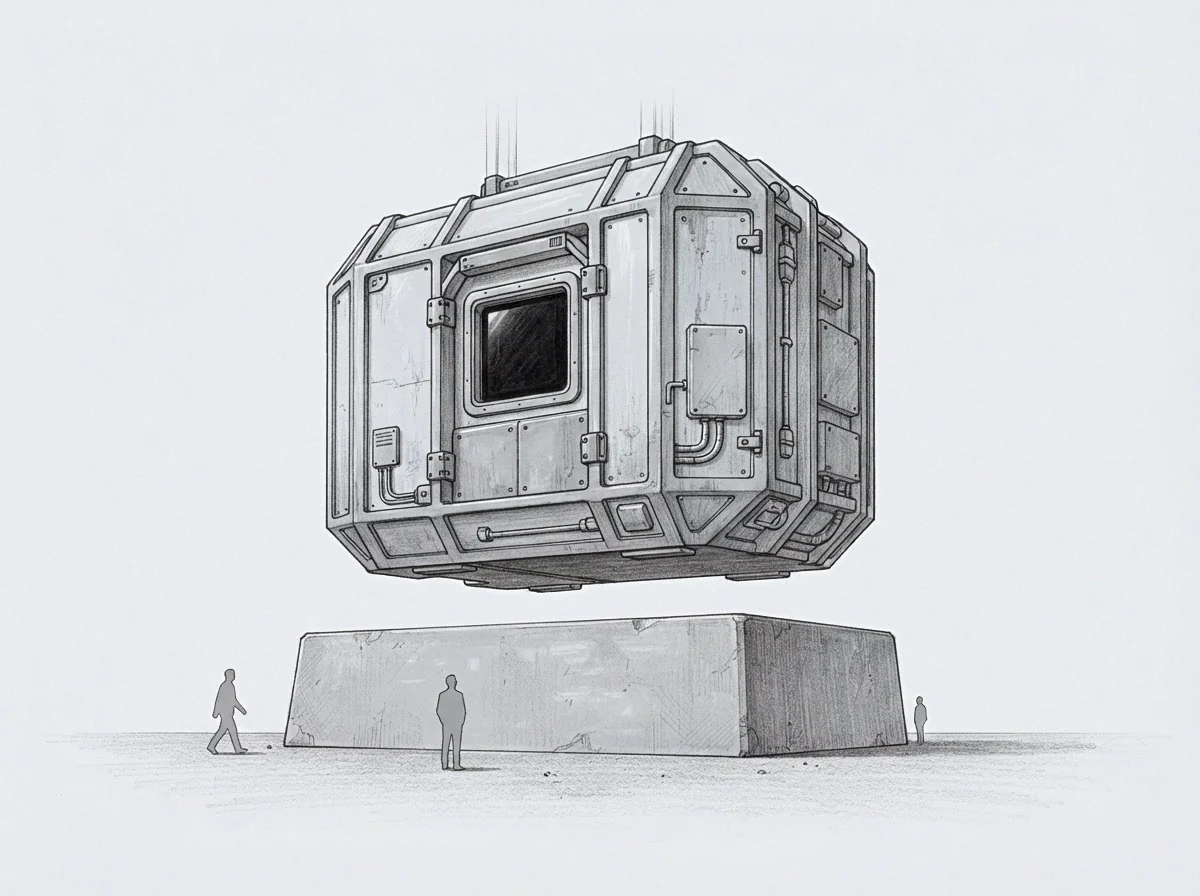
Disturbance Skew
Disturbances rarely follow normal distributions across orthogonal axes. Environmental forcing functions routinely exhibit directional bias, where positive shocks arrive as gradual drifts and negative shocks hit as sharp impulses. Measuring the directional derivative of state variables under stress reveals the underlying loss function.
When an operational boundary sits equidistant between positive and negative excursion limits, the system operates in permanent proximity to its unrecoverable perimeter.
The gradient of recovery expenditure defines the boundary profile. Moving outward on a safe vector incurs marginal monitoring cost. Moving outward on a compromised vector initiates compound restitution fees.
Directional boundaries must reflect this differential slope. The safe zone takes the shape of an asymmetric convex hull, pulled inward along steep penalty gradients and extended outward along shallow restitution slopes.
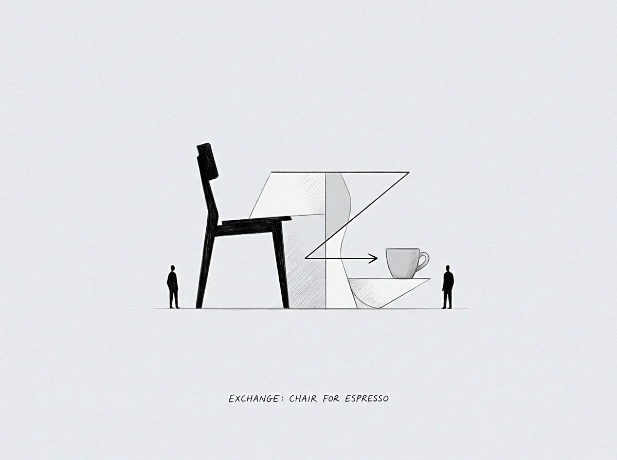
Where Disturbances Skew The Operating Margin?
Tracking the directional velocity of state perturbations exposes boundary erosion before threshold breaches occur. Systemic resilience depends on whether damping forces scale proportionally with displacement speed. When damping coefficients fail under directional acceleration, outer perimeters contract automatically.
The operator models boundary contraction as an operational coordinate rather than an emergency exception.
The following parameters govern directional boundary calibration across asymmetric operating profiles:
- Disturbance skewness measures the third standardized moment of environmental shocks along each operational axis to locate directional vulnerability.
- Restitution latency records the exact duration required to restore nominal baseline states following a standard deviation unit displacement.
- Gradient penalty calculates the marginal increase in stabilization expenditure incurred per unit of excursion beyond the steady-state zone.
- Coupling coefficient traces the cross-axis transmission rate where instability on an exposed vector bleeds into shielded operational reserves.
Boundary placement mirrors the ratio between directional shock amplitude and replenishment speed.
Buffer depth expands along vectors where restitution cost grows exponentially with displacement distance.
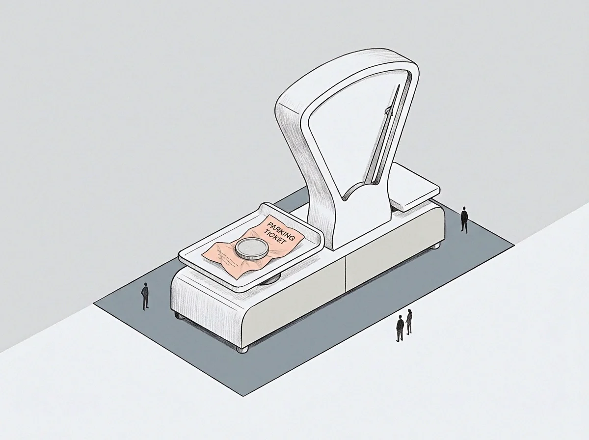
Valve
Throttling Mechanisms
Static boundaries break under dynamic loads. Preserving systemic integrity under asymmetric disturbance regimes demands rate-dependent control valves that restrict throughput along exposed vectors before boundaries suffer physical contact. A reactive threshold triggers intervention after boundary violation occurs.
A rate-sensitive valve monitors the rate of approach, restricting operational velocity when vector acceleration outpaces available recovery damping.
Dynamic throttling introduces directional friction. When environmental volatility spikes along a specific vector, the control system increases the transaction cost of further excursion along that axis. The organisation slows deployment rates, demands higher collateralisation for new commitments, and shortens verification intervals.
Shielded axes continue operating under standard tolerances, preventing the systemic paralysis that follows indiscriminate global throttling.
| Disturbance Profile | Boundary Geometry | Throttling Trigger | Restitution Friction |
|---|---|---|---|
| Isotropic Gaussian | Symmetric Circle | Static Level | Linear Constant |
| Skewed Momentum | Shifted Ellipsoid | Velocity Threshold | Quadratic Rise |
| Impulsive Asymmetric | Truncated Polygon | Acceleration Derivative | Exponential Penalty |
| Coupled Cascade | Contracting Paraboloid | Cross-Axis Coherence | Discontinuous Cliff |
The operational friction applied to a vulnerable axis preserves structural reserve volume for unpredictable cross-vector shocks.
Budget allocation reflects the practical reality that capital deployed along the high-friction vector cannot be recalled in time to prevent structural failure on the exposed flank.
Band

Boundary Positioning
Calibrating directional operating bands requires formalising the trade-off between operational throughput and boundary breach risk. A tight band reduces downside exposure while truncating productive capacity. An excessively wide band captures marginal upside while exposing systemic solvency to low-frequency tail events.
The operational boundary sits at the inflection coordinate where the marginal return on outward expansion matches the expected cost of directional containment.
Mapping empirical system trajectories against theoretical bounds reveals operational drift. Operators track directional occupancy histograms to discover hidden boundary compliance failures. When operating states cluster persistently against an outer boundary on a single vector, the system indicates that nominal tolerances fail to match underlying environmental drift.
The correct adjustment contracts nominal capacity to realign the envelope with true restitution physics.
A stable boundary profile maintains equal failure probabilities across axes possessing unequal shock distributions.
Uncertainty remains regarding the precise mathematical formulation for cross-vector contagion when simultaneous shocks strike orthogonal axes under non-linear damping conditions.